ECE 3140 Final Project: Reaction Time Game
Completed during my spring semester, Junior year.
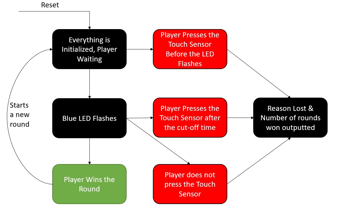
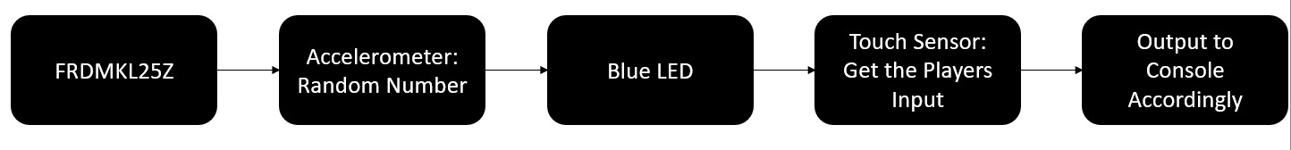
Our Single Player Reaction Time game is a simple game which tests a players reaction time. The basic design of our game is simple, a player must wait for the FRDM KL25Z's Blue LED to turn on and press the Capacitave Touch sensor as fast as possible to try and win a round. The player must be careful to press the touch sensor early or they will lose the game. Additionally, the player must be careful to not take too long to press the touch sensor after the LED flashes or they will also lose the game. Lastly, the player needs to be careful since the LED does not blink at the same time for every game, so they cannot predict when the LED will flash. After the player loses a round, the number of round which they won is outputted and the reason for why they lost is outputted to the player.
The motavation for this project was to build upon what we had learned about in the course, especially the real time processes. Our goal was to create a game utalizing Lab 5 and parts built into the board such as the Touch Sensor and Accelerometer to learn how to build upon out knowledge from the course. We learned how to work together in a group and to figure out how to get the Touch Sensor and Accelerometer to work based off the examples to do what we wanted. We learned how to modify those files to create our reaction time game. Lastly, we learned how to read the example files and use the manual in order to figure out what everything does, which is beneficial becuase we will most likely need to know how to do something like that in our jobs later in life.
To create our reaction time game, we utilized our code from Lab 5 in order to implement real-time processes, so we could keep track of the current time of the program in order to determine the players reaction time when they press the touch sensor. This meant that we would be specifically need to utilize our process.c and realtime.h files, as well as the utils.h, utils.c, 3140_concur.h, 3140_concur.c, and 3140_2.s for other necessary functions. We needed to have Real-Time processes in order to flash the LED at a random time and the current time to calculate the reaction time and to keep track of when the Real-Time processes would begin. The other files gave us useful functions to allow us to flash the LED's a specific color. We also had to come up with a way to flash the LED at a random time so that the user could not predict when the LED would flash every time. This was done by reading a the accelerometer, giving us different values each time due to noise. Even if the board was stationary, the noise of the accelerometer would give us a different value each time, giving us a new random time each time. Once we had the ability to create Real-Time Processes and keep track of the current time, we were able to begin working on implementing the touch sensor in order to read the players input.
To implement the touch sensor, we looked at the example given in the SDK example (tsi_4) to understand how we needed to initialize the touch sensor and how the capacitive touch sensor is determined to be pressed. Once the touch sensor was pressed, we would utilize the TSI Interrupt to let the program and board know the button has been pressed. Once we had a functional touch sensor, we were able to create a run.c file which would act as our program for running our Reaction Time Game. From here we had two Real-Time Processes, one to flash the blue LED and one which was a wait function which would allow us to use the Touch Sensor Interrupt that would interrupt when it was pressed. From here we would then determine the outcome of the game depending on the reaction time we calculated. Running in debug mode would allow us to see the outputs from console each time, depending on the output of the game and to see it on each reset of the game.
Our first task was implenting the touch sensors. Using the example give by going to:
File->New->Import SDK->FRDMKL25Z->Driver Examples->TSI_v4,
We were able to modify the implementation, which became our tsi.c. In tsi.c we had to initialize the Touch Senosor so that it reacts when the player pressed the sensor. The initilization we used is identical to the SDK example, which ensures the we are setting all of the correct pins, ports, etc. for the touch sensor correctly. After the Touch Sensor is intitialized, we then needed to create an interrupt to activcate then the Touch Sensor was activate. This was done in the same way as the example, but with some modifications.
In modifying the interupt routine, we had to make sure that it would not take too long in order to not violate interrupt behavior, but still do what we needed it to do. Our first modifaction was to implement that when the touch sensor was activated, we want to calculate the reaction time of the player. Once the button was pressed, we would set our boolean pressedTS which is important so that we don't run the game program over and over again when it has finished and later in run.c. Once the reaction time was calculated, we needed to determine if the player had pressed the button early or not. If the player pressed the button early, we would not toggle the blue LED since the process had not begun yet. If the player pressed the button appropriately, the blue LED would be turned off. We also had to put a condititional variable inside of our interrupt to make sure that it would only register one one press to the touch sensor.
After we had our reaction time, we could then calculate the outcome of the game accordingly. If the polayer pressed the button too early, they would lose the game and the Red LED would turn on. If the player presses the button after the Blue LED was turned on and before the cutt-off value, the Green LED would flash siginifying victory. The cutt-off was determined by figuring out the how quickly the capacitive touch sensor reacts to being pressed and an interval of a second or two, given the user enough time if they are paying attention to press the touch sensor fast enough. If the player was too slow, they would lose the game and the Red LED would turn on
Additionally inside the tsi.c we had many helper functoins. The first function was simple and was called in the run.c file to recieve the random arrival time for the Blue LED so we would be able to calculate the reaction time properly. The second was a function which would return if the game was done or not. For the game to be finished, the player has to have pressed the touch sensor at some point before the wait process finsihed. This function was needed in run.c to determine if the touch sensor had been pressed before the LED had flashed, so that the game knew that it did not need to flash the LED or if the wait process didn't need to wait anymore for the touch sensor interrupt. The third helper was to flash the green multiple times to signify that the player won the game. The next one was using inside the wait process to be used when the waiting time was over and the player had never pressed the touch sensor yet. This was used as a "4th" scenario to make sure the player didn't leave and come back after the game was done and not have an output of a loss. The last helper was the one which determine the three main scenarios for the game and was called when the touch sensor was activated and only outputs for the first press of the touch sensor.
The main purpose of process.c was to give us the current time and to have Real-Time Processes, but we also needed a quick modifcation to it in order to calculate the difference between the current time and the time of when the Blue LED was flashed. This function would be called when the Touch Sensor Interrupt happened when the touch sensor was pressed. This allowed us to calculate the reaction time of the player. This was our only modifcation to process.c.
The testing scheme for our final project differed from most other labs, however, it was the most similar to Lab 1 where we had to test Morse Code. When we wanted to verify the correctness of the game, we would use the run.c file and check to see the outcome of the game by pressing the touch sensor at different times and recording the result. This allowed us to verify that each different outcome of the game worked as it was supposed to and test to make sure it was working properly.
Since we were using Lab 5 process.c, we made sure that our Real-Time Processes were being scheduled correctly. First we only had one Real-Time process, however, after testing we realized that we needed to have a second one which acted as a “wait” that would be a period of time for the player to press the touch sensor after the Blue LED flashed. Depending on when the player pressed the touch sensor during this wait Real-Time Process the correct outcome would be selected or if the player never pressed the touch sensor it would output accordingly when the wait finished.
We also utilized break points to figure out certain positions in our code, such as when the TSI interrupted our program to see what the current time was or if we were getting a random value each time for the start time of the Blue LED flash. Using breakpoints at specific positions in our code allowed us to verify that everything was being written to the stack and registers correctly. Looking at the main function we set up breakpoints each time we called a function in process.c, tsi.c, or another file. This is how we ensured that they were setting up everything since we are unable to run actual test cases similar to previous labs because we required a user input to verify the correctness of the program.
Breakpoints allowed us to find bugs in our code such as when we began the project by trying to output the reaction time when the player won or was too slow. However, after much testing and reading the manual for the board, we were unable to figure out the actuation time for the capacitive touch sensor. This meant that through our rigorous testing of finding the accurate reaction time, we could find a value for the touch sensor actuation time to be around 750ms - 850ms, but decided to not output a reaction time since it would not be accurate given the conditions and decided to only implement the possible conditions for the player to win the game.
Additionally, the breakpoints are what allowed us to verify that we had the random number generator giving us a new number every time the game was played. This was particularly difficult since srand(time(NULL)) or srand(time(0)) does not work with the board since it would give us the same value each time we reset, so we would need to read a value from the accelerometer in order to get noise and find a different random value on each instance of the game running. The random number generator was crucial to our design because we needed to make sure that it flashed the Blue LED at different times so that the player could not predict the output and would accurately test their reaction time. In using the accelerometer, we had to make sure that even when the board was stationary, it would still output a different random time each time it was given a value of srand to start with.
In order to test each outcome for the game we needed to make sure that everything was running smoothly. Once the processes and the touch sensor were working, we were able to begin to verify every outcome. To test if the player pressed the button too early, we needed to make sure that we pressed the touch sensor right after it was initialized, before the Blue LED blink process arrival time. To test if the player were too slow, we waited for a period of time after the Blue LED flashed, but before the wait process finished in order to verify that we would lose the game. To verify the winning condition, we made sure to press the touch sensor as fast as possible after the Blue LED blinked. Lastly, to verify that the player did not ever press the touch sensor, we started run.c and did nothing and got the correct output.
The run.c file handled running the reaction time game, which ran similary to test cases in previous labs. Additionally, run.c was responsible for setting up the acceleromenter for creating the start point for srand to give us a random number. This file conatined the main function which setup the LED's, setup the TSI, and ran the processes. Our run.c would calculate the random time for the Blue LED Real-Time process. This was to ensure that the player could not predict when the LED would flash everytime and keep them on their toes. A second process was used as a wait function so that it could be interrupted in order to determine what the current time was and the outcome of the game. This file would create both processes and run them, giving us our reaction time game which would could be played by one player at a time.
When writing up the code, we used Chris’s computer and compiled and tested it on there as well, while all of us were looking through the code and talking throughout, figuring out how to write the functions. We did this over Zoom and would periodically allow the other to have remote control over the file so we could add our ideas and test different ideas. Throughout the whole process, we worked on creating the functions, debugging them, and testing our code and we did this simultaneously together on zoom for the process of coding. We all worked collaboratively on the design and coding together through zoom and on testing and debugging. When we ran into issues we were unable to solve, we figured out out who was able to go to Office Hours the soonest and they went to Office Hours and reported back to the group. Once we had our full design, we made sure everyone had the files so we could run it on everones computers and we could then debug our code together and make sure that it worked for all of us. We also shared our results with each other during testing through text message videos and Google Drive to ensure everything was the same, even though we had our expected results, this was to check it further.
For the website we divided it up into sections. While we were all on Zoom together, we each worked on a part of the website. The respective parts for the website were: Chris (technical description), Matt (system overview, resources), David (Work Distrobution, Introduction, Testing). Once all the parts were finsihed, we made sure to go over each others sections and add any details that may have been missing.
For the video we all worked together and recoreded it at the same time over Zoom, each talking about a section which we felt the most confident in. Matt edited the video since he had experience with editing videos before.