Introduction
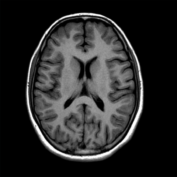
For the final project of ECE 4250, students were tasked with creating and developing an automatically segmenting brain MRI scan that can be used to focus in on anatomical regions of interests, or ROIs. For my final project implementation, I decided to use an affine transformation model that would achieve better alignment than geometric transformations for my optimized approach. Before going into detail, I need to address what I used in the previous milestones that I continued to use in the final submission. In the first task, Milestone 1, I figured out how to load the MRI data and created a function named, middle_coronal_slice, which was used to convert the image data and extract the middle coronal slice. For Milestone 2, students were tasked with creating a four-parameter geometric registration function, simply called geometricRegistration, that was used to compute and save the optimal parameters for the image as well as the geometric, transformed image using said optimal parameters. However, the rest of my implementations changed in the final version.
The Transform Function
When deciding how to improve the transform function I created in Milestone 2, I thought using an affine transformation would be the right way to go. According to MathWorks, “Affine transformation is a linear mapping method that preserves points, straight lines, and planes. Sets of parallel lines remain parallel after an affine transformation. The affine transformation technique is typically used to correct for geometric distortions or deformations that occur with non-ideal camera angles” [1]. Instead of using warpAffine from the cv2 library, I decided to use AffineTransform and warp functions from the skimage.transform library. By using the AffineTransform and warp functions instead of warpAffine, I was able to create a new transform function that would also allow me to scale the image in question. This change eliminated the need for generating and operating on new transformation matrices, smoothing out the process.
The Loss Function
Optimizing the loss function was a key step in making the process work better. When searching skimage.measure library, I came across the compare_ssim function. This stood out to me because instead of trying to calculate the fmin of each image like in Milestone 2, I could now compare how similar each image was to the others in the set. SSIM is defined as: “The Structural SIMilarity (SSIM) index is a method for measuring the similarity between two images. The SSIM index can be viewed as a quality measure of one of the images being compared, provided the other image is regarded as of perfect quality” [2]. Using SSIM, I was able to get a much better Dice score when submitting my evaluation on Kaggle. This operation did take a lot longer to execute, but the trade off in accuracy is definitely worth the extra time it needs in order to finish.
The Optimize Function
To improve my optimize function, I only changed the execution of the optimized_params variable. Originally, I used the scipy.optimize.fmin function from the scipy library. This function performs the optimization by “Minimiz[ing] a function by using the downhill simplex algorithm” [3]. Looking deeper into this function, it “Uses a Nelder-Mead simplex algorithm to find the minimum of function of one or more variables” [3]. While this is definitely a good function to use, I wanted to use a function where I could directly change the algorithm being used to something that has better performance. Luckily, that other option was the scipy.optimize.minimize function from the same library. This function allows the user to input which algorithm he or she wants to use. So, after trying the different options that were compatible with my set up, I stuck with BFGS as this gave me the best performance during the optimizing stage.
Filtering the Images
During Milestone 2, I noticed a lot of noise in the images when compiling everything for the submission. Researching ways to reduce or eliminate the noise in the images, I came across the skimage.restoration library which included a denoise function: denoise_nl_means. This function, which “performs non-local means denoising on 2-D or 3-D grayscale images” [4], takes an input image and reduces the noise in the image. In the figure below, one can see the positive effect of denoising an image.

Implementing this type of filter definitely helped my Dice score as the images are now clearer. It is also important to discuss why I chose the denoise_nl_means function instead of the other types. Using trial and error and learning what each function does, I discovered that the bilateral denoise function denoises the image by averaging the pixels based on their spatial closeness and radiometric similarity [4]. The Bregman denoise function performs a “total-variation denoising (also know as total-variation regularization) tries to find an image with less total-variation under the constraint of being similar to the input image” [4]. During my trials of the different denoising functions, the non-local means denoising function resulted in the best clarity, so I chose this denoising function.

Results
In Figure 2 above, I present the different Majority Voting Based Label Fusion images for each image. Each image shows the specific regions of interest: the Left Cortex of the brain, the Cerebral White Matter in the left side of the brain, the Right Cortex of the brain, as well as the Cerebral White Matter in the right side of the brain. In each image, the four parts became more visible, in part due to using a slightly larger data set by combining the validation and training image sets together. I thought that by adding these data sets together, I could get better, more accurate results. However, I did not test this idea, and went ahead purely using both data sets combined together. If I were to repeat this project, I would definitely try the two data sets separately and then together to validate whether the data improved.
Error Analysis
After executing the code for the final part of this project, I noticed that something was wrong with my images. In Milestone 2, when compiling the images for the transformation function, I rotated the image data in the beginning when sorting the images into their respective image sets in order to align them vertically. However, since I had made changes to improve my transform function for the final version, these changes did not work well with the rotated image. Figure 2 shows the final result, while Figure 3 shows the errors I encountered when including the rotation inside the middle_coronal_slice function. As one can see, the images are missing a lot of data, compared to the final result I got from removing the rotation function. Simply rotating the images at the end was definitely the better way to go, as this rotation does not change any of the data before any of the segmentation functions are executed.

Ethical Considerations
Thanks to new and improving technologies, medical imaging is becoming much more accurate and useful, especially when it comes to diagnosing and treating diseases. However, these technologies are not immune from abiding by ethical principles, especially protecting patients and their medical data. These images used in the MRI scans are patient data and must be protected due to laws regarding patient confidentiality.
I found an article published by the University of Minnesota titled, “An Ethical Roadmap for Breakthrough MRI Technology.” In this article, the author, Kevin Coss, discusses how new MRI technology can lead the way into providing better help to those who need it, in part thanks to a new portable MRI scanner. “‘Instead of participants traveling to the scanner, the scanner will come to them,’ said Francis Shen, JD, PhD” [5]. Some of the more challenging ethical questions with this technology stems from securing patient data and ensuring patient consent.
One concern that engineers have is the use of artificial intelligence. The design team needed to address the potential bias that could possibly arise from the use of artificial intelligence when analyzing the data [5]. The article also goes on to explain that with the emergence of artificial intelligence, doctors will be able treat patients who are economically disadvantaged, live in rural areas, and/or are part of racial and ethnic minority groups that are current underrepresented in neuroimaging [5]. This ability to capture more data is incredibly important since artificial intelligence improves with more data and time. It is also important that if the analyzed data is corrupt or returns an error, engineers need to be able to fix the errors in the artificial intelligence code to ensure that the error doesn’t replicate.
Jupyter Notebook and Results
References
- [1] “Affine Transformation.” MATLAB & Simulink, www.mathworks.com/discovery/affine-transformation.html. (visited on 05/18/2021).
- [2] Wang, Zhou, et al. “ The SSIM Index for Image Quality Assessment.” The SSIM Index for Image Quality Assessment, CNS, 11 Feb. 2011, https://www.cns.nyu.edu/~lcv/ssim/.
- [3] Scipy.Optimize.Fmin — SciPy v1.6.3 Reference Guide. https://docs.scipy.org/doc/scipy/reference/generated/scipy.optimize.fmin.html. Accessed 24 May 2021.
- [4] https://scikit-image.org/docs/dev/api/skimage.restoration.html#skimage.restoration.denoise_tv_bregman
- [5] Coss. “An Ethical Roadmap for Breakthrough MRI Technology.” Inquiry | Office of the Vice President for Research, 16 Sept. 2020, https://research.umn.edu/inquiry/post/ethical-roadmap-breakthrough-mri-technology.
